Discover more about fibre optic splicing
EDP Europe is a distributor of Fujikura fibre optic splicers. In this Guide To Fibre Optic Splicers you’ll find out what fibre fusion splicing is, why choosing the correct fibre optic splicer is important and the how the process of fibre splicing works.
What is a fibre splicing?
Fibre splicing is the process of joining two fibre optic cables together. There are several instances where this may be necessary including, repairing a damaged fibre cable, extending a fibre cable link or installing a new fibre tray or IANOS Splice Module where the installation fibres need to be spliced to the pig tails within the tray.
There are two main ways of fibre splicing fusion splicing or mechanical splicing:
- Fusion Splicing – Fusion splicing requires the use of a fibre fusion splicer which welds the two fibres together in a permanent connection. There are various types of fibre fusion splicer available, with advanced models such as the Fujikura 90S+ offering core-to-core alignment. Fusion splicing provides the lowest loss, less reflectance, strongest and most reliable method of joining two fibre cables together.
- Mechanical Splicing – Mechanical splicing enables splices to be made quickly and easily and is usually achieved through the use of a junction where two of more fibres are aligned and joined in a self-contained assembly.
What Fujikura fibre splicing machine should I choose?
A fibre splicing machine is required to conduct a fusion splice. Fujikura are a market leader in manufacturing fibre fusion splicers but which of their fibre splicing machines should you choose?
The answer is dependent on the type of fibre you are fusion splicing. If you are splicing mainly Single Mode cables then the need for a splicer with true core alignment will be greater, particular where there may be a mix of Single Mode cables from different manufacturers or different eras. The Fujikura [90S+ is a true core alignment splicer that features a programmable automatic wind protector that clamps, aligns the cores and splices in seconds. Core alignment splicers are ideal where the core in a fibre cable is not concentric (centred), as the alignment motor moves in multiple directions and will compensate for this lack of concentricity and still align the cores. Active V-Groove Alignment splicing machines are capable of splicing Single Mode fibre cables providing the fibres have good core concentricity, this is due to there being less movement in the alignment motor and why they are less expensive than a true core alignment splicer. Cladding Alignment splicers are ideal splicing machines for splicing Multi Mode fibres where the core is larger. With cladding alignment there is minimal alignment motor movement, making them less appropriate for splicing Single Mode cables without suffering some signal loss.
Why the use of a fibre optic tester is important in the fibre splicing process?
The use of a fibre optic tester plays an important role in the fibre splicing process. Firstly, the use of a Visual Fault Locator (VFL), such as the AFL VFI4, or Optical Time Domain Reflectometer (OTDR) can help locate where a fibre optic cable is damaged and where the fibre splice needs to be carried out. Secondly, once the fibre splice has been conducted a fibre optic tester can be use to check the splice is good and in the case of the AFL FlexScan FS300 OTDR certify the performance of the fibre optic cable. For more information on network cable testers please refer to our ‘Guide To Network Cable Tester Equipment’ page.

How to prepare the optical cable using a fibre cleaver to perform a fusion splice.
Before preparing an optical cable to fusion splice using a fibre cleaver, it is important to follow best practice safety procedures and wear safety glasses.
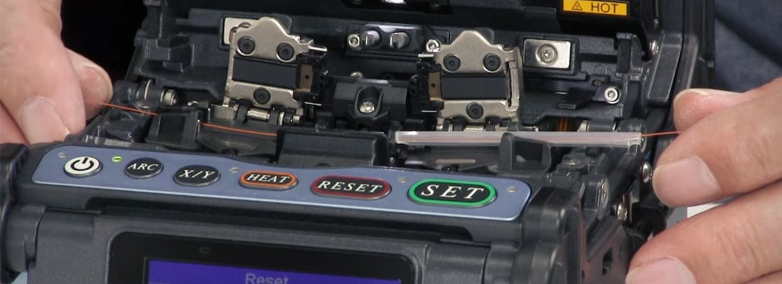
To prepare the two ends requiring splicing is a straight forward process. Take one of the fibres and slide on a heat shrink protective sleeve, this will be used later in the fusion splicing process. The next stage is to remove the outer protective jacket so that the actual fibre is exposed. Using a specially designed fibre stripping tool first remove the buffer tube layer, then using the next groove in the stripping tool remove the cladding; being careful throughout the stripping stage not to damage the core, as this can lead to it breaking. Next using an appropriate fibre wipe and cleaning solution wipe the core to remove any foreign particles. The next step is to cleave the core. Depending on the type of fibre cleaver being used this stage will vary based on the cleaver’s instructions, but in all cases fibre cleaving is about trimming the core down to the correct length for splicing. Using a cleaver results in the end of the fibre being as square and flat as possible to minimise loss when the splice is made. The cleaned fibre should then be placed in the clamp within the fusion splice and the cleave process repeated on the second fibre. Great care should be taken with the discarded pieces of fibre from the cleaving process, some fibre cleavers for example the Fujikura CT50 feature a receptacle that collects these ends for safe disposal. When both fibres are clamped in place within the fusion splicer the fusion splice can be carried out. Depending on the splicer model being used the alignment will either need to be completed manually or will automatically be conducted by the splicer. Once the splice has been made the joined fibre should be carefully removed and the heat shrink protective sleeve slid over the join. This is then placed into the tube heater to shrink the sleeve to complete the splice. The final stage is to test the optical cable to ensure the splice is good.
Why achieving a good fibre splice is vital to fibre optic cable transmission speed?
Fibre optic cable transmission speed varies depending on the type of fibre cable being used and the distance the data has to travel. Fibre optic cables come in two types Single Mode (OS1) and Multi Mode (OM1, OM2, OM3 and OM4). Single Mode fibre is more expensive as it transmits data over a greater distance up to 40km and beyond. Multi Mode fibre operates over shorter distances, but can carry multiple data signals, and comes in two core sizes 62.5/125 microns (OM1) and 50/125 microns (OM2). OM4 Multi Mode cables are laser enhanced versions of OM2 and OM3. Each time there is a connection between the transmitter and the receiver, part of the signal is lost. A connection is classed as either a physical connection, for example connecting to a fibre patch panel, or a mechanical or fusion splice. Therefore, being able to produce a good fusion fibre splice can help minimise this loss. An experienced installer can produce a splice in Multi Mode fibre resulting in an average loss of 0.3dB and in Single Mode fibre typically less than 0.05dB. This keeps the loss in fibre optic cable transmission speed down to a minimum.


